Implementation elements of tire partition technology
1. This utility model relates to the field of tire technology, specifically to a tire partition structure and a tire bead storage device.
2.The main function of traditional tire forming machine tire partitions is to protect the tire beads and prevent them from sticking to each other. However, this type of tire bead separator can easily cause the separator to stick to the tire bead, making it difficult to separate the separator from the tire bead during manual winding, especially during automatic winding. This not only increases the difficulty of manual operation, but also causes instability in automatic winding.
3.The main purpose of this utility model is to provide a tire bead partition structure and a tire bead storage device, in order to solve the problem of inconvenient removal of tire beads on the partition device in the prior art.
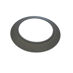
4. In order to achieve the above objectives, according to one aspect of the present utility model, a tire bead partition structure is provided, comprising a partition body, the partition body being a ring-shaped structure for carrying tire beads, the partition body comprising an inner ring plate and an outer ring plate, the inner ring plate and the outer ring plate being spaced apart along the radial direction of the partition body; Support component, the inner side of the support component is connected to the inner ring plate, and the outer side of the support component is connected to the outer ring plate. The support component is used to carry the tire bead, and there is at least one hole on the support component to reduce the contact area between the tire bead and the support component when the tire bead is placed on the partition body.
5. Furthermore, the support component comprises: multiple support ribs, which are spaced apart along the circumferential direction of the partition body between the inner ring plate and the outer ring plate, wherein one end of the support ribs is connected to the inner ring plate, the other end of the support ribs is connected to the outer ring plate, and a gap is formed between adjacent two support ribs.
6. Furthermore, the inner ring plate and the outer ring plate have a common axis and are arranged at intervals along the vertical direction. The inner ring plate is located above the outer ring plate, and the support ribs are inclined between the inner ring plate and the outer ring plate to achieve positioning under their own weight when the tire bead is placed on the support component.

7. Furthermore, the top of the inner ring plate is provided with a first positioning portion, and the bottom of the inner ring plate is provided with a second positioning portion, so that adjacent two bead partition structures are connected by clamping the first positioning portion and the second positioning portion.
8. Furthermore, the first positioning part comprises a first annular convex rib, which is used to support the inner ring plate of adjacent bead partition structures, so that when two adjacent bead partition structures are connected, the supporting components on the two bead partition structures are spaced apart by a predetermined distance.
9. Furthermore, the first positioning portion further comprises multiple first positioning card slots, which are arranged at intervals along the circumferential direction of the inner ring plate. The second positioning portion comprises multiple second positioning plates, which are arranged at intervals along the circumferential direction of the inner ring plate. The multiple first positioning card slots are arranged in one-to-one correspondence with the multiple second positioning plates, so that when adjacent two tire ring partition structures are connected, the second positioning card on one tire ring partition structure is arranged in the corresponding first positioning card slot of the other tire ring partition structure to stop the relative rotation of the two tire ring partition structures.
10. Furthermore, the top of the outer ring plate is provided with a second annular convex rib, which is used to support the outer ring plate of adjacent bead partition structures, so that when two adjacent bead partition structures are connected, the supporting components on the two bead partition structures are spaced a predetermined distance apart.
11. According to another aspect of the present utility model, a tire bead storage device is provided, comprising multiple tire bead partition structures, which are stacked in sequence along the vertical direction, and the tire bead partition structure is the tire bead partition structure described above.
12. Furthermore, the tire bead storage device further comprises a bottom plate, which is arranged at the bottom of the tire bead storage device. Multiple tire bead partition structures are stacked on the bottom plate, and a positioning component is provided on the bottom plate for fixing the tire bead partition structure connected to the bottom plate.
13. The tire bead partition structure using the technical solution of the present utility model is mainly applied in the field of rubber tires for storing tire beads. Specifically, the partition body adopts a circular ring structure similar to the tire bead structure, and the tire ring is set on the support component between the inner ring plate and the outer ring plate. Due to the rubber material used for the tire bead, which is relatively soft and has a high surface viscosity, multiple pores are set on the support component to prevent the tire bead and the support component from sticking together, thereby reducing the contact area between the tire bead and the support component, reducing the adhesive force between the tire bead and the support component, and facilitating the removal of the tire bead from the partition structure.